VFD-60 Vibrator control
VFD-60 drive is used to control the functioning of an electromagnetic vibrator. The control is based on two basic parameters: frequency and amplitude of the oscillations.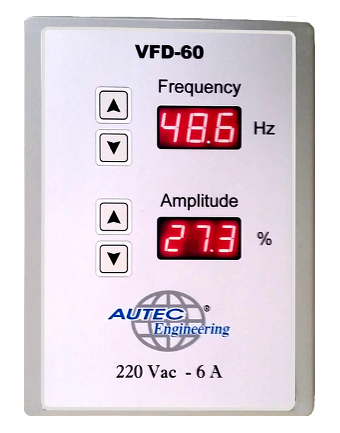
The single-phase VFD-60 drive is easy to install and use. All you need to do is to connect the drive to the 220Vac electrical network (the drive is available also in 110Vac version) and the output clamps to the vibrator. This model is suitable for controlling electromagnetic vibrators with up to 6A absorption.
The operating frequency of the vibrator can be set up independently from the network frequency, allowing for lower electricity consumption. Furthermore, connecting the acceleration sensor to the vibrator it is possible to stabilize the amplitude of the oscillations in a totally independent way from the load (closed loop).
The device can be programmed locally with its front display interface, remotely through a LAN port or through 4-20 m-A interface.
DATA SHEET
POWER SUPPLY AND OUTPUT
Supply voltage (line): 110-230 Vac ± 20%
Vibrator nominal current: 6 A
Line frequency: 50-60 Hz
Efficiency: > 95%
Output frequency regulation: 40 ÷ 120 Hz
Output amplitude regulation: 1 ÷ 100%
Operating temperature range: -10 ÷ +60 °C
INTERFACE
Local: Keyboard + Display - Oscillation amplitude and frequency setting
Ethernet: 100 MBit/s - Personal Computer or PLC (application software for Windows 7/10 provided) to set the parameters to the desired value: in this modality the resonance frequency can be searched, in order to obtain a lesser energy absorption.
Analogue: 4-20 mA - The parameters values can be set through current signals (4-20mA)
FUNCTIONING
VFD-60 device can be operated both without the acceleration sensor (open loop) and with the vibration sensor (closed loop). By closing the control loop through the acceleration sensor the vibrator can be taken to the resonance frequency, obtaining the smallest energy absorption without any damage risk for the vibrator.
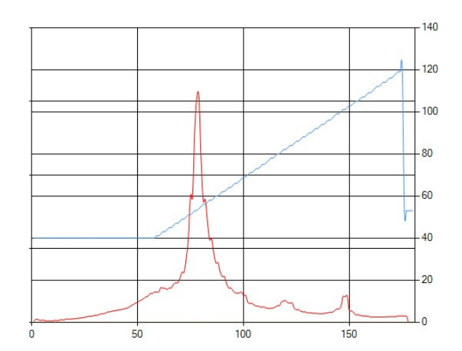
The opposite graph shows the ramp in frequency (blue line) with which – through a command from the PC – the resonance point search test can be carried out (frequency from 40 to 120 Hz). The red line shows an acceleration peak corresponding to the frequency of resonance (53 Hz in this example).
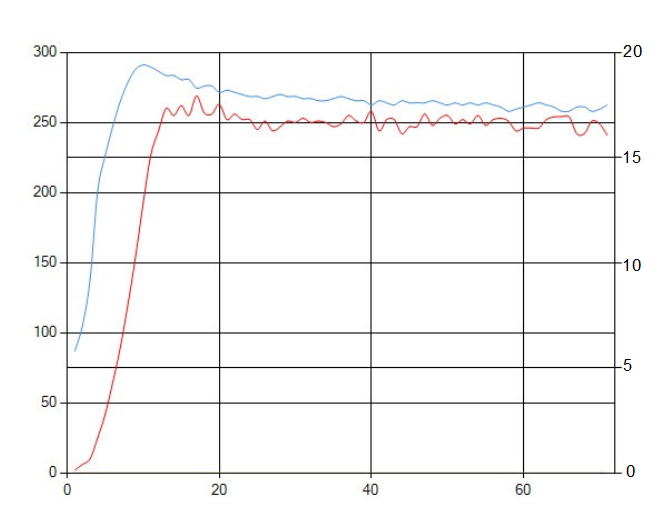
The opposite graph shows the power (blue line) referring to the right column (17% duty cycle), required to move the vibrator at the resonance frequency and have an acceleration (RMS) red curve of 250 points, left column.
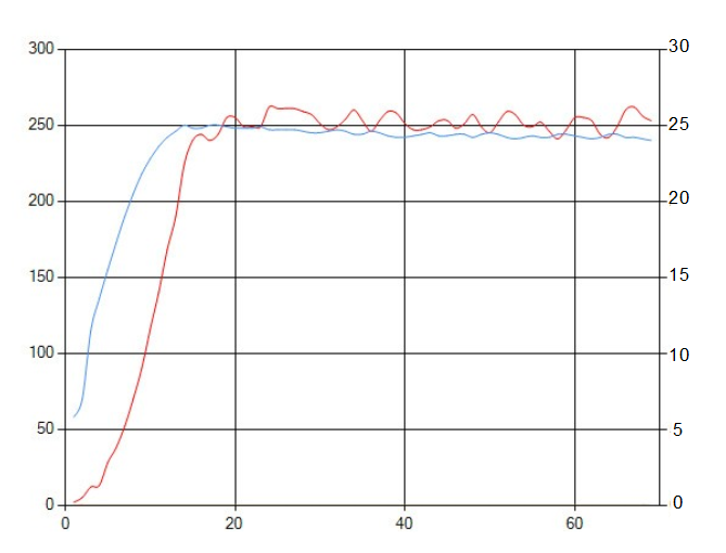
The opposite graph shows the power required when operating at network frequency with open loop. As it can be noticed, in this case to obtain the same 250 points acceleration (RMS) – red line – the blue line needs to reach 24%, 7% higher, meaning greater consumption.